

Gear geometry
Profile, lead, pitch or other characteristics specified for the part.
Gear tooth and dimensional inspection using gear measuring systems and coordinate measurement. Define the characteristics and reports required for your part.
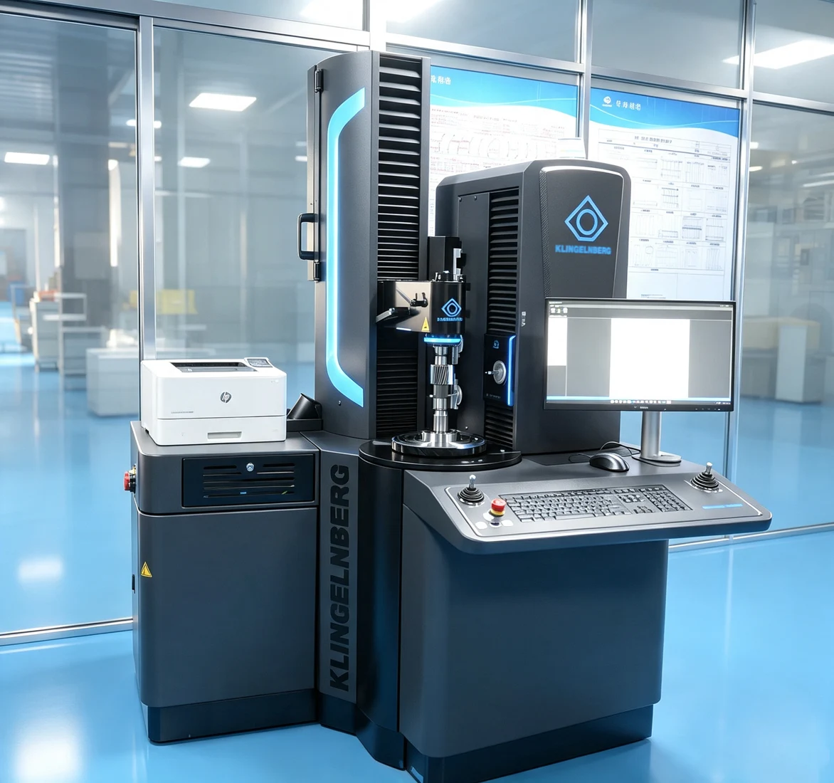
Gear inspection and dimensional inspection answer different questions. A tooth measurement examines the gear geometry; a coordinate or dimensional check examines journals, faces, bores and other interfaces. Both may be needed to establish a complete acceptance record.
The inspection base includes a Klingelnberg P26 gear measuring center, a Hexagon GLOBAL S coordinate measuring machine and Econ gear testing systems. The measurement plan is defined by the drawing, specified standard and agreed reporting requirements.
Profile, lead, pitch or other characteristics specified for the part.
Runout, locating faces and journal-to-tooth datum relationships.
First-article or batch documentation agreed for the production stage.
Gear measuring center for applicable tooth-geometry checks.
Coordinate measuring machine for component geometry.
Gear testing equipment for the specified inspection requirements.
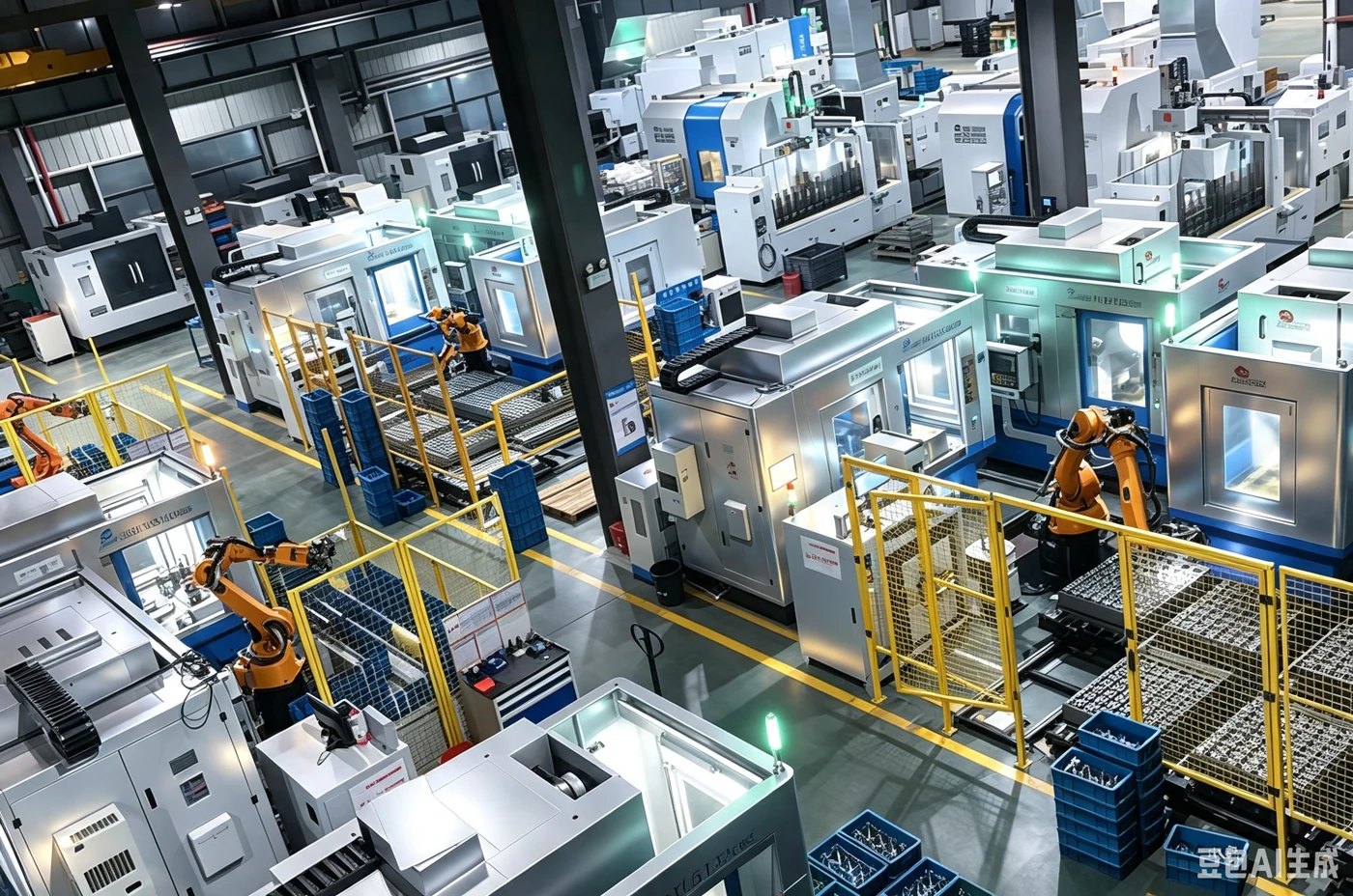
Identify the drawing revision, standard and special characteristics.
Separate tooth checks, dimensional checks and material-condition records.
Define sampling, units, traceability and record requirements.
Compare the measured characteristics with the controlled acceptance limits.
| Review item | What to define |
|---|---|
| Acceptance limits | Drawing tolerances and the applicable tooth accuracy standard. |
| Datum scheme | The reference features used for assembly and measurement. |
| Record scope | Required report format, sampling and material/treatment evidence. |
| Approval process | First-article, PPAP or other project requirements to be reviewed. |
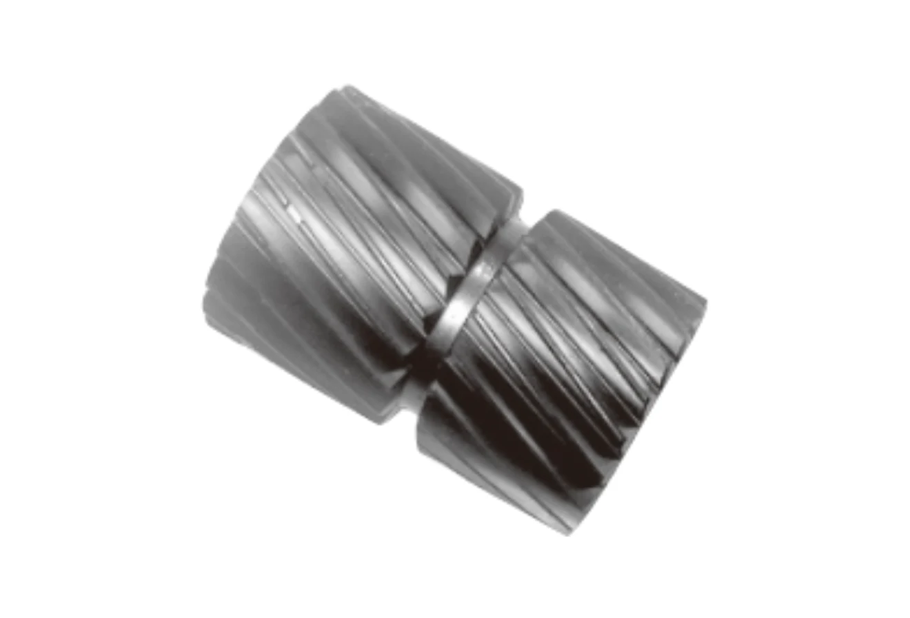
Custom helical gears and combined gear parts for vehicle and industrial transmissions.
View product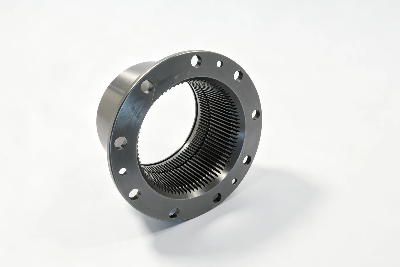
Internal ring gears for planetary reducers, wheel-end drives and compact transmissions.
View product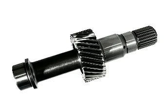
Combined shaft and spline features for power transmission assemblies.
View productA gear drawing package should define the teeth, the mounting interfaces and the relationship between them.
Read guideInclude the latest drawing revision, quantities and the application. Add material, treatment and inspection specifications where these are already defined.
Request a gear quotationSend your drawing, required quantity and application. We will review your part and contact you about the details needed for a quotation.